Some commentators have recently blamed “solar advocates” in Pakistan for overlooking the inability of solar systems to provide reactive power and inertial support to the electric grid. They are apparently correct, but, as we clarify below, a deficiency only arises if distributed solar is viewed through the lens of the traditional grid, which relies on serving consumers via gigantic, central-station power generation using extended transmission and distribution (T&D) systems. Distributed solar and similar technologies have opened new vistas of serving consumers’ electricity needs at or near their sites, making the conventional grid largely redundant.
The conventional grid (generation, transmission, distribution, and delivery systems and facilities taken together) is a complex undertaking and very difficult to explain in non-technical terms. Two critical concepts to understand are: (i) a consumer’s demand for “electric power” (kW or MW) at any given instant for different services (heating, cooling, lighting, preserving food and medicines, industrial processes, and others); and (ii) the duration for which this demand remains on the grid, “electric energy” consumed (kWh or MWh).
Electric grids are built and operated to ensure that sufficient generating and T&D capacity and fuel stocks are available to serve consumers’ aggregate demand for power and energy anywhere in their systems, from the next moment to the next couple of decades, or even longer.
Modern grids operate on the principles of electromagnetic induction (alternating current “AC” systems). In these systems, power flows back and forth 50 or 60 times every second, depending on where in the world we live. This is in sharp contrast to direct current or “DC” systems in which power flows in one direction only.
Throughout the system (from generation to end-users), electric grids rely on materials that oppose the flow of power in various forms: resistance, inductance (magnetic fields), and capacitance (electric fields). The last two are also called inductive reactance and capacitive reactance, and all three collectively “impedance”.
A crude analogy may help clarify the issue. From high school physics, we may recall that “work” or “energy” was defined as the product of “force” and “displacement”. Suppose some weight is lying on a flat table and we want to push it away a foot on the table. Obviously, we need to exert some force to overcome the friction of the table surface.
We should not assess a new technology using a framework that was devised for an entirely different set of technologies, as this would not only be unfair but also tantamount to comparing apples with oranges
It should not be difficult to appreciate that this force is needed only when we apply the force exactly behind the weight and in parallel with the table surface. If, for any reason, we cannot do that, we will need some extra force to accomplish the same task. We face a similar situation when supplying electricity.
In electric circuits, “power” is defined as the product of “voltage” and “current”. In AC systems, both the voltage and current follow a sinusoidal waveform (Figure 1). They rise from zero to a maximum and then fall back to zero again in the first half cycle, and then repeat the same pattern but in the opposite direction in the second half cycle. This cycle is repeated 50 to 60 times every second. In a perfect world, we should have power (S) equal to voltage (V) times current (A).
If the voltage and current rise and fall in step with each other, we call them in phase, which they are in DC circuits and in purely resistive AC circuits. If they are not, which is the case in most AC circuits in practice, we call them out of phase. The degree depends on the size and nature of the reactance in the system. This situation is similar to the example in which we cannot apply force in the ideal direction and are compelled to apply some extra but useless force.
The impedance in AC systems not only resists the flow of power but also displaces voltage and current from each other, making less force available to do useful work. Power in the system is no longer a simple product of voltage and current, but now the product of voltage and the part of the current in phase with it.
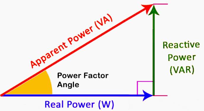
Apparent power S is still voltage times current (VA, kVA, or MVA), but the power available to do useful work is reduced. We call it “active power” (Watt, kW, or MW) and the other part that does not do any useful work but is still needed to overcome reactance “reactive power” (VAr, kVAr, or MVAr). The presence of reactive power in the grid is a necessary evil, and not a beneficial resource (Figure 2).
No element is purely resistive, inductive, or capacitive, but is designated so for the property that dominates. Each of these properties poses some unique challenges to the grid, individually as well as collectively. Inductive and capacitive reactance in a circuit oppose each other and, if equal, would leave the system to deal with the resistive part only, meaning no reactive power.
This is the basic principle behind the AC power system design and operation, that is, minimising resistance and reactance and, where this cannot be done, by employing reactive power compensation.
Power supply systems must not only cover the power losses but also deal with the fact that voltage and current are no longer in phase with each other but are displaced in time by an angle called the power factor. Most of the reactance is due to the nature of the load and only part of it relates to T&D systems. If not handled effectively, it increases losses and voltage drops in the T&D systems and compromises system capacity.
We use three fundamental parameters, “frequency”, “voltage”, and “current”, to design and operate the grid. Consumer facilities are also rated accordingly. Since frequency is kept fixed throughout a power system, we can ignore it. Grid operators keep the voltage fixed for a specific category of consumers (within 5% of nominal) to maintain the pressure and let the current vary based on the power ratings of consumers’ appliances and equipment.
The pressure is maintained at various points in the grid, including at the consumer site through voltage control techniques, including mitigating reactive power needs by loads and the T&D systems. Generators can serve reactive power demand to some extent, but this severely undermines their capacity to serve consumers’ power needs.
Most loads are inductive in nature, so where these can be clearly identified (like in industries or large commercial facilities), we require them to install capacitors at their sites. Where it is difficult to isolate, we add capacitor banks on the distribution feeders or substations. On transmission systems, we use reactive power compensation equipment.
Transmission lines, however, are unique as when lightly loaded, they exhibit capacitive character (needing inductive compensation); when heavily loaded, they exhibit inductive character (requiring capacitive compensation).
It is also not correct to say that consumers pay for real power only. They are charged in a variety of ways: (a) exclusively via volumetric consumption (kWh or MWh); (b) by a two-part tariff (energy and power demand both); (c) for large consumers via additionally charging them for their reactive power demand (VAr, kVAr, MVAr); and (d) via imposing power factor penalties if it falls below a certain threshold like 85 or 90%.
Due to their static nature, photovoltaic (PV) systems deployed even at utility-scale do not produce any reactive power or inertia. That is true, but these are not issues that can be managed cost-effectively. Furthermore, we should not assess a new technology using a framework that was devised for an entirely different set of technologies, as this would not only be unfair but also tantamount to comparing apples with oranges.
Figure 1: AC Waveform
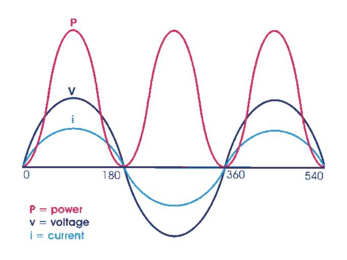
Figure 2: Power Triangle